Shore piling is uneconomical Piling operation creates noisy environment When excavated deep shore pile may get collapse To prevent collapsing of shore pile rock anchoring is carried out. Chapter 5 presents five design methods to determine the static capacity of single piles in both cohesive and cohesionless soils.
Sheet Pile Shoring Design Propped Structural Guide
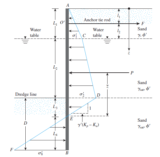
In this example we will design a cantilever sheet pile wall supporting a 10 ft excavation.

. Sengupta Senior General Manager ITD Cementation Kolkata-700072 India. Width of excavation 30ft Depth of excavation 25ft Pile diameter 2ft Pile face to face distance. Chapter 4 gives an overview of the static design process for timber piles.
This design example is basically the same as Track 1 Example 1 with additional construction control involving pile retaps or restrikes at 3 days after EOD. Chapter 5 Single Pile Design 51 End bearing piles 52 Friction piles 53 Cohesion piles 54 Steel piles 55 Concrete piles 551 Pre-cast concrete piles 56 Timber piles wood piles 561 Simplified method of predicting the bearing capacity of timber piles Chapter 6 Design of Pile Group 61 Bearing capacity of pile groups. The site is a small commercial facility that hosts receptions and social events and therefore has a large number of parking spaces.
For our purposes we will further simplify the process by increasing the entire penetration below the dredge line by 20 thus d 122 02 122 146. The design conditions we had designed for various seawall components are as per engineering manual. 22 Rock Anchoring In the event that the uncovering profundity or additional charge is higher cantilever shore heap should be secured at.
This is the objective of this design guide Offshore Pile Design. Manual 1110-2-1614 is used to design seawall element like Water level Wave period Armour unit Layer thickness Core Secondary Layer Toe Protection and Filter Layer. Shore piles support the surrounding loads and prevent the surrounding soil from breaking in at the time of construction.
By the term marine pile it is commonly meant the piles used as a structural part of jetties wharves dolphins and other such near shore and off shore structures. This video explains how cantilever pile wallsheet pile walls are designed. WHAT IS SHORE PILE Generally piles are sunken support for building.
Tables 1 and 2 present the soil properties and the stratigraphy respectively. Example pile quantity can be reduced by 8 to 10 in a 40 ft 12 m diameter shaft if location tolerance is controlled to within -1 inch 25 mm in plan compared to an industry standard. It should be noted that the resistance factors with special consideration of pile setup are for 7-day retap.
Shore piling refers to give support to the construction site by inserting steel or concrete or wooden shores into the ground. Chapter 7 discusses design considerations for Marine applications. Helical pile for new construction 8-10 design example 4.
Design Example - Step 4 Preliminary Pile Detail CasingCasing 55 in diam. Light commercial structure 8-12 design example 5. A vertical wood metal or concrete support for a building or other structure that is driven into the ground Shore piling is a commonly used term before installation of the mat foundation of the building needs to be done.
Helical pulldown micropiles for 8-18. Sheet Pile Design by Pile Buck and the online help for SPW 911 explain how that is properly applied. SPECIAL CONSIDERATIONS IN MARINE PILE DESIGN AND CONSTRUCTION PS.
Yeild strenght of steel fy Ultimate concrete strenght fc Allowable strenght. Design examples design example 1 atlas resistance piers symbols used in this design example. Design example 3.
The estimation of seawall design is done with PWD schedule of rates. Shore pile design example Written By jasperklaich60398 Tuesday May 10 2022 Add Comment Edit. Permeable pavement level 1 and sheet Flow to Conservation area The site plan and drainage area map for Example 1 is shown in Figure 611.
The Figure below presents the project model. Table 3 presents the external loads. 375 in wall Plunge Length Bo n Centralizer Top of Dense Gravel Plunge Length B o Centralizer Top of Dense Gravel Case 1 Type B Reinforcing Bar 225 in Grade 520 d Zone Neat Cement Grout Reinforcing Bar nd Zone Neat Cement Grout.
SR pile length within the liquefiable layer I minimum moment of area and A. 30 inch Support is provided at 125 ft from top. Chapter 8 discusses pile.
This design guide is limited to the design of. Limit the slenderness ratio SR of the pile. View Design of Shore Pilexls from GENERAL 432 at Bangladesh University of Eng and Tech.
PILES AND SHORE PILES Generally piles are sunken support for building. Chapter 6 covers the design of timber pile groups. Designexamples 61 Chapter 6.
Limit the ratio of the later load to critical buckling load to about 13 to have a safety imaging against buckling. By the term marine pile it is commonly meant the piles used as a. Based on the widest possible critical analysis of the state of the art and on the recent research result including work by ARGEMA on the behavior of piles subjected to static and cyclic loading in tension and in compression.
Table 4 presents the wall properties. Shore piles support the surrounding loads and. The total length of the sheet pile wall is h d 10 146 246.
This design example demonstrates how to estimate the nominal driving resistance.

Shore Pile Design Pdf Pressure Chemical Engineering
Shore Pile

Shore Pile

Shore Pile

Shore Pile

Shore Pile

Shore Pile Deep Excavation Engr Md Sajjak Hossain Youtube

Shore Pile
0 comments
Post a Comment